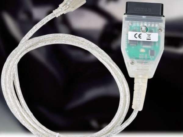
What does the switch do on the cable?
The switch connects pin 7 to pin 8. On certain older vehicles such as E39 this will allow access to additional modules in addition to DME. On DCAN cars connecting pin 7 to pin 8 will disable all DCAN functionality.
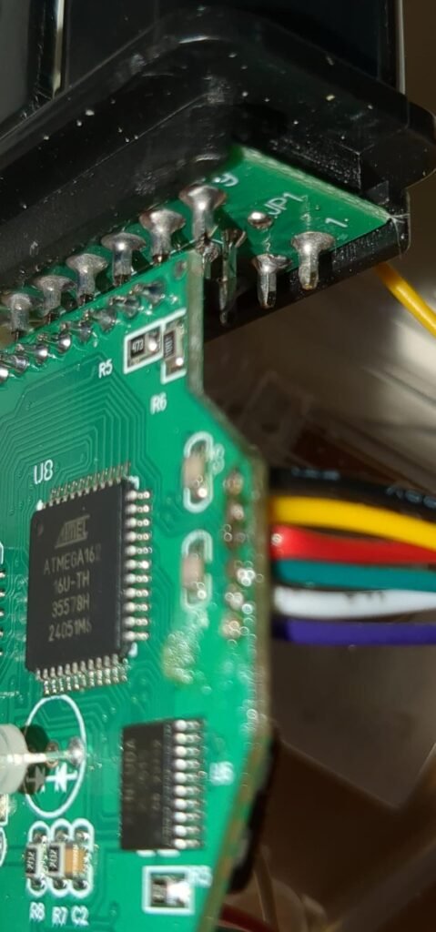
What is being reprogrammed.
On the K+DCAN cable there is a Atmel Atmega162 that contains the firmware for the cable. This chip must be reprogrammed.
Why reprogram the cable?
Increrased stability, speed, compatability and the ability to use additional software. With the updated firmware M3/M5/M6 DME (MSS6X), E6x, M5/M6 SMG (GDSMG3), and E9x GM Auto (GM1912) ECU’s can be flashed without corruption.
In addition you can experience the following benefits; faster CAN communication (block size 0 and no separation time), allows configuration of CAN mode all the time, not only after power on, allows configuration of the CAN parameters (block size and separation time), correctly displays the ignition status (only available for K-line mode), contains a bootstrap loader that allows firmware update without opening the device, reduced power consumption due to use of sleep mode, can use BTT quickflash programs.
What tools do I need?
You will need a Arduino (Uno, R3, etc), some jumper cables, solder or some kind of touch pins, a usb cable to connect from the PC to the arduino.
First step is to convert the arduino to an atmel programmer.
- ARDUINO IDE DOWNLOAD (Tested was the Windows MSI Installer): https://www.arduino.cc/en/software
be sure to install drivers from ADAfruit industries, - In the “Tools” Menu click Board and secect Arduino Uno or the kind you have
- In the top “Tools” Menu select the Port: “Your port” -> Your COM Port
- In the top “File” Menu select Examples -> 11.ArduinoISP -> ArduinoISP
- The Arduino is now an Atmel programmer and this program is no longer required
Connecting the programmer to the cable
This requires 6 connections to be soldered OR your may fabricate some kind of touch pins.
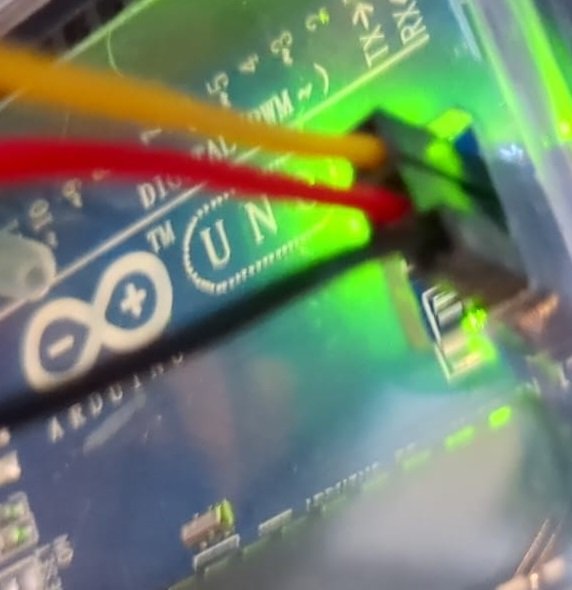
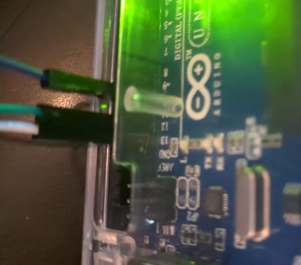
- BLACK = GROUND —> ARDUINO ICSP PIN header GND
- YELLOW = VCC+(POWER) —> ARDUINO ICSP PIN header VCC
- RED = MOSI —> ARDUINO ICSP PIN header MOSI
- GREEN = MISO —> ARDUINO PIN 12
- WHITE = SCK —> ARDUINO PIN 13
- PURPLE = RESET —> ARDUINO PIN 10
Sorry about the colour mix up I solded the yellow wire by accident instead of the red and didn’t feel like back tracking.
Programming the Atmega 162
The Arduino programmer is powered by the USB and the Atmega does not require and additional power to program thus no external power supply is required.
- Head on over to AVRDUDELESS – A GUI for AVRDUE and downlaod it.
https://github.com/ZakKemble/AVRDUDESS/releases/
(tested was the portable version but the full setup is recommended) - Head on over to github:uholeschak and download the latest release (compiled)
https://github.com/uholeschak/ediabaslib/releases - Right Click on the release and unzip it
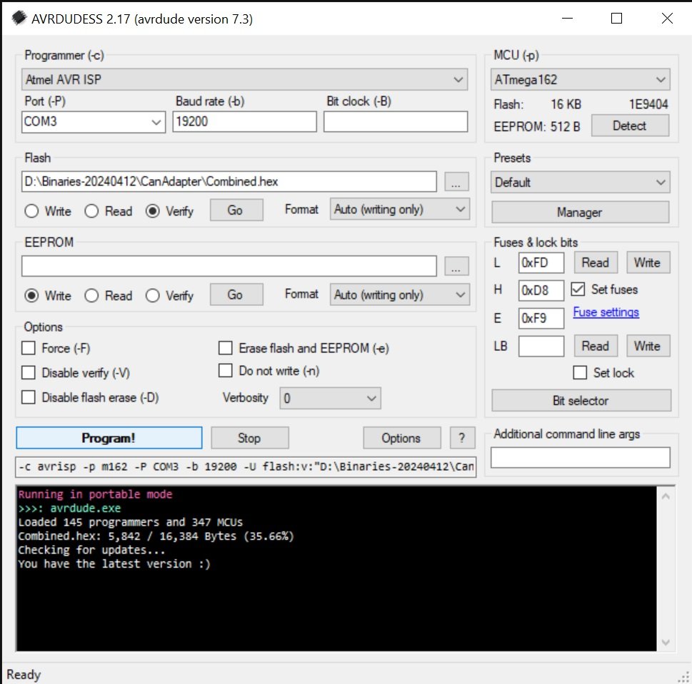
- Open AVRDUDELESS
- Select Programmer: Atmel AVR ISP
- Select MCU: ATmega 162
- Click Detect
- Read fuse bits to populate them (check them later)
- Select flash the “\CanAdapter\Combined.hex”
- Select “Program!”